Miniexfire
MINIEXFIRE
Five years after the launch of the EXFIRE360 control unit; SV is expanding its range of control units with the compact version of its modular system; with the aim of completing the range of applications for small systems.
Why “Mini”
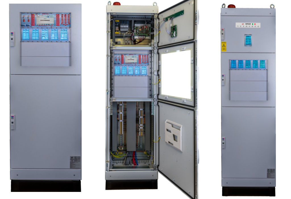
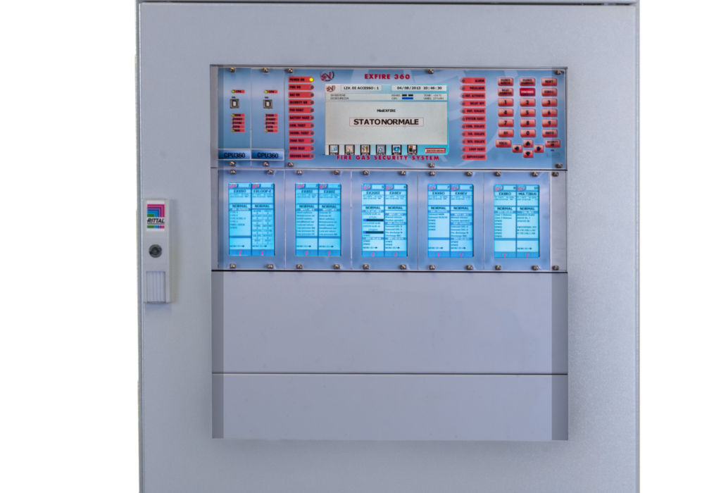
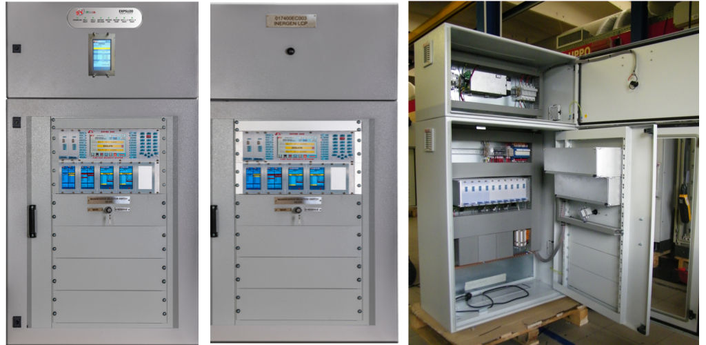
MINIEXFIRE is a mono-chassis control unit capable of housing up to 10 input / output cards; accompanied by the respective touch-screen graphic displays that make it its characteristic feature. The EN 54-4 power supply system is scaled to an independent unit (called EXPSU20) with a maximum current intensity of 20 A redundant.
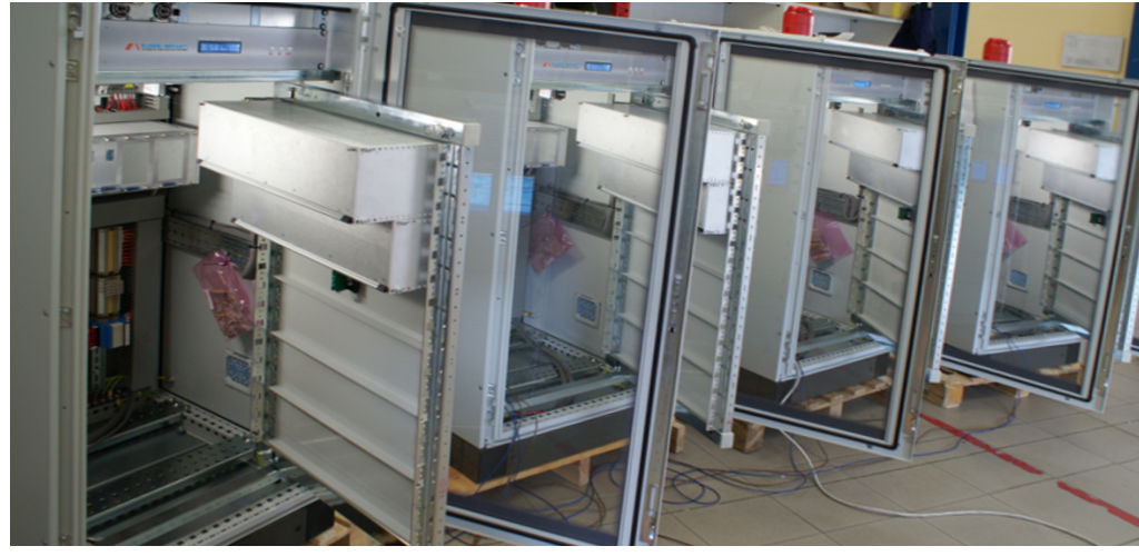
MINIEXFIRE is therefore housed in a cabinet with dimensions equal to 1000 mm (h) x 600 mm x 400 mm; which is combined with the power supply equipment – and the relative batteries with a capacity up to 80 Ah – with dimensions of 400 mm (h) x 600 mm x 400 mm.
MINIEXFIRE is designed for wall installation; ideal in those environments where the composition of the system or the limited space does not require a floor-standing wardrobe.
What Benefits
MINIEXFIRE inherits the characteristics and performances from EXFIRE360: modularity, simplicity of the operator interfaces (which are real graphic displays for each board), CPU redundancy, diagnostics, automatic addressing, hot back-up, inter-chassis CAN communication, supervision with Enterprise software, interfacing with third-party systems
miniexfire also borrows the certification assets from the “mother” control unit (with the modifications associated with the smaller dimensions), making it usable for fire detection, gas detection and automatic fire extinguishing.
Finally, EXFIREmini separates the power supply equipment into an independent unit, which can be supplied separately from the control unit.
Regarding the regulatory aspects, the miniexfire control panel complies not only with the mandatory requirements of the EN 54-2, EN 54-4 (fire detection systems) and EN 12094-1 (fire extinguishing systems), EN 60079-29-1 ( ATEX gas detection systems) but is certified to perform a series of optional functions contemplated by the same standards and commonly required in industrial fire-fighting systems.
Consider, by way of example, the availability of a standardized input and output interface for the bidirectional communication of the miniexfire control unit with third-party systems, or the control of fire protection systems, or, again, the management of extinguishing groups. reserve and supervision of the pressure signals (high / low) of the systems themselves.
The EXFIRE360 control unit was therefore developed by implementing targeted technological solutions to meet the requirements of the EN54-2, EN54-4, EN12094-1, EN60079-29-1, GOST, soon, UL864 and IEC61508 TUV standards, protocol used by HOCHIKI APOLLO.
This section introduces the implementations that will be carried out both on the EXFIRE360 control unit and on its compact version to meet the requirements of points 4.29 (release of extinguishing agents for selected discharge zones) and 4.30 (activation of alarm devices with different signals) of the standard EN12094-1.
Compared to the EX6EV-C board currently certified for shutdown; SV intends to propose a new configuration in which the role of the individual input/output channels is not defined a priori and in which the logics are performed directly by EXCPU360.
To explain how this new configuration works; refer to the diagram of a detection and extinguishing system on two zones shown in the following figure:
Optional requirements
The boards used to manage this system will be 2 EX6EV; 2 EX6SO and 2 EX8SI (or an EXLOOP-E in addition for the detection part only).
Analyzing in detail the individual signals, we will have that:
The detection will be performed by acquiring at least 2 conventional signals per zone (EX8SI or EX6EV card) or through addressable devices (EXLOOP-E card). The solenoid activation logic will be defined in the control panel configuration program (SV Protection);
The shock buttons will be acquired under a conventional input (EX8SI or EX6EV). The control panel configuration program will be modified so that a specific function can be defined for each input channel (eg manual release, abort button, etc);
The same principle will also be used for all the remaining inputs (emergency stop and extension buttons, automatic / manual mode selectors; main / reserve selectors, high and low pressure switches, generic system supervision signals);
As for the outputs, the EX6EV board will remain the board responsible for controlling the zone solenoids (directional valves) and will also be able to activate the optical / acoustic pre-discharge and discharge warning devices (point 4.30). The functionality of the individual outputs will be defined in the configuration program of the miniexfire control unit. an EX6EV card will be provided for each discharge zone;
The EX6SO boards will instead take care of the command to the solenoids of the banks of main / reserve cylinders common to both extinguishing systems; as well as the implementation of any additional alarm devices. The function of the individual outputs will be defined through SV Protection;
To meet the requirement of the standard according to which a generic fault must not affect more than one discharge zone; the commands to the common solenoids will be redundant (in the example above you will therefore need 8 outputs in total, for this you will use 2 EX6SO);
Control of auxiliary devices such as ventilation block; closing shutters etc. it will be carried out through the unsupervised outputs of the EX6EV board; the intervention logic will be freely programmable by the user through SV Protection;
The control of the system status and of the activation logics will be performed through the EXCPU360 control units; according to the functions defined in the configuration program.
For example; the inhibition of the discharge in the presence of a fault on an emergency extension device; will be decided by evaluating the status of all the configured devices; as HOLD type in Protection. In this way it will also be possible to configure multiple input or output lines with the same functionality;
The signals about the status of the discharge zone (activated / released / fault / etc.) Will be shown on the MODLCD display of the relative EX6EV board;
Through the menus of the same display it will also be possible to modify the settings (discharge delay / reset inhibition time / etc.) Of each extinguishing zone; as well as disable (at access level 3) the download itself.
The previous example relates to a “complete” configuration. With the same type of logic it will in any case be possible to manage even less complex systems (for example a single zone with a high pressure switch; a discharge button and a single solenoid to be controlled).
Unlike the previously certified configuration, locked on using an adjacent EX8SI and EX6EV card; the new approach will make it possible to cover plant and regulatory requirements with a single card (EX6EV); to be expanded with additional input cards (EX8SI or EXLOOP-E) or output (EX6EV or EX6SO) depending on the system characteristics.
Paragraph 12.3.2 of EN 54-2 provides for the possibility of installing the CCS on several enclosures; provided that the integrity requirements of the transmission media referred to in 12.5.3 are met.
The chassis of the EXFIRE360 control unit can therefore be installed in separate enclosures from the miniexfire control unit; specifying that these containers will be equivalent to those of the EXFIRE360 control unit in the “mini” version.
These concentrators will be powered by the power supply equipment referred to in point B) or; alternatively, from the power supply unit of the EXFIRE360 control unit, according to the installation requirements.